|
|
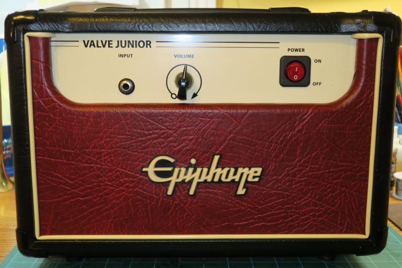
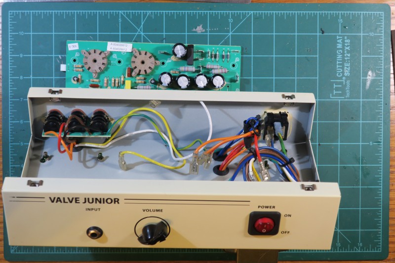
The stock Epiphone Valve Junior amp is a Vox AC-4 clone. The preamp vacuum tube is a 12AX7. The output tube is an EL84 tube in a single-ended configuration. Notice only one control and that is volume. You control tone and overdrive using your guitar controls and the volume.
The Valve Junior was available from 2005 to 2012. I think it was about $200 to $250 new, but I picked this new condition one on eBay for about $90. Wikipedia has a nice history article about the Value Junior.
I am sorry to say I did not capture recordings of this amp in its stock configuration. However, if you want to skip the comments and pictures and hear the final results, please skip down to the sound clips.
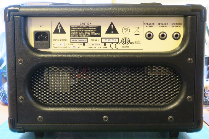 |
There is an IEC power cable connection on the left. There are 4, 8, and 16 ohm speaker jacks on the right. No fancy output loops on this one.
The transformers and output tubes hang down from the circuit case.
The cabinet is built like a tank with birch plywood and metal corner guards.
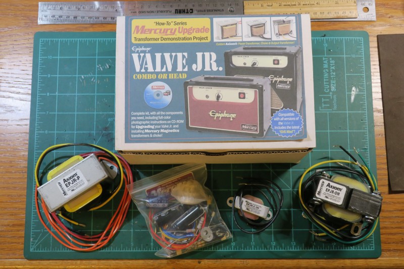 |
The Mercury Magnetics instructions are well done with schematics, step by step instructions, photos, and construction tips.
The kind of modification should only be undertaken if you are good with a solder iron, and you have tools and electronic circuit skills. This is not a simple mod of removing a few components and adding others.
 |
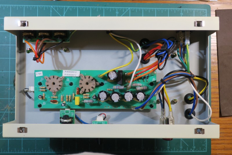 |
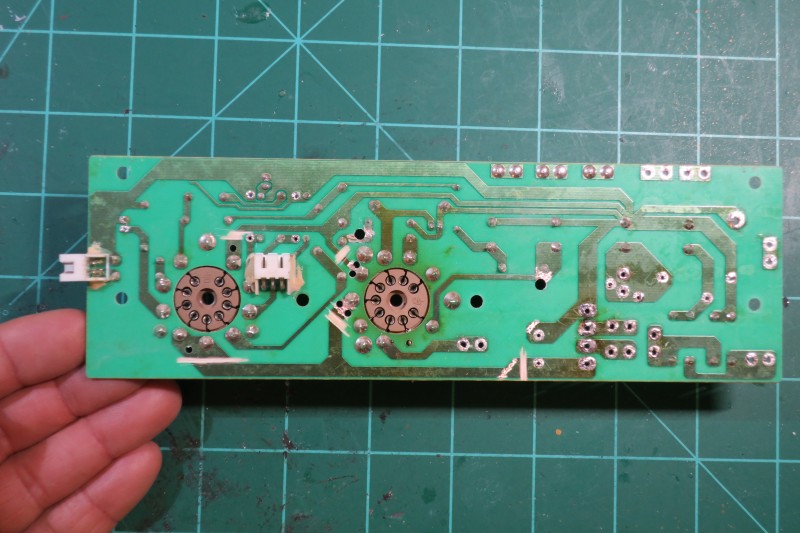
Notice that the green board is rather small and printed. Printed circuit boards in amplifiers are not very desirable. They can crack if you flex them. They are not easily repairable or modified. They are tough to debug and take measurements from.
I was surprised at all the clips and socket connections. These look rather expensive and add cost to the amp. Perhaps they are there for manufacturing purposes making it easy to swap out a bad component during the testing phase.
 |
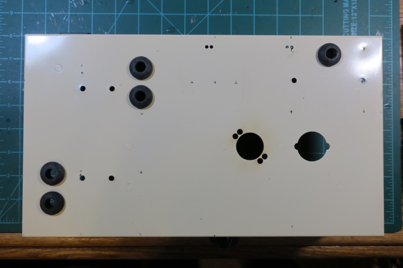 |
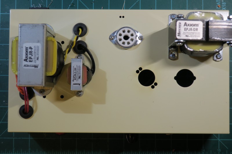
You can also see markings and awl-punches for the new holes that need to be drilled. The new transformers have different footprints than the old ones, and we need a new hole for the 6V6 tube addition. The new choke for the amp needs some mounting holes too.
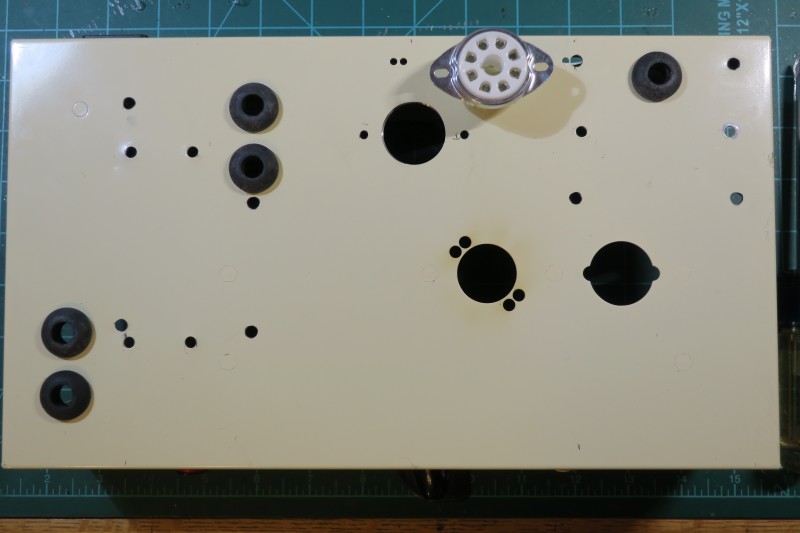 |
I placed the new 6V6 tube socket next to its final destination and made sure it fit.
 |
Some of the older components have to be removed also to prepare for other modifications. Some of the big power-sucking resistors are removed. Some of the smaller signal resistors are also removed.
The chunky, disconnected, four-lead component at the top is a DC rectifier module. It turns the wall alternating current into a steady, level, direct current. It's leveling capacitor can go too. One of the features of this modification is to switch from DC tube heaters to AC heat. More on this later.
 |
In this step I also show some cuts to the printed circuit board lands. The big land at the top of the circuit board is ground. The big land at the bottom is the DC power. The cuts are primarily to disconnect the DC power from the tube heaters So you see two cuts near the 12AX7 preamp tube socket on the left, and two cuts near the EL84 output tube socket in the middle. The cuts disconnect the two heater pins for each socket.
A few holes are drilled also. Most of these are to connect the new AC hearers to the tubes. More on this later.
 |
Like a transistor, one of the functions of vacuum tubes (or valves) is to act as an electronic signal amplifier. There is one input called the collector which is a source of current and an output called the emitter which is the drain of current. A third input called the base or gate controls the flow from collector to emitter from full speed down to nothing. It is very much like a flood gate controlling the flow of a mighty river.
Vacuum tubes also have collectors, emitters and gates, but they are often named after the physical elements inside the tubes: the emitter is also called a cathode, the gate is called a grid, and the collector or anode is called a plate. Many tubes have additional screens between the gate and plate which help control "splashing" of electrons hitting the plate - these improve efficiency of the tube.
A vacuum tube needs a large reservoir of electrons to form a current. This is where the heaters come in. They are like a filament in a light bulb producing a river of electrons. The gate or screen controls the mighty flow from cathode to the plate.
Heaters can be DC, which produce more heat and shorten the life of the tube, or they can AC, like our light bulbs, which produce less heat and last longer. However AC can introduce hum noise and so they are often twisted to help cancel out noise.
 |
The smaller component in the middle is a choke. A choke is an inductor that blocks high frequency AC signals and passes DC. The choke smooths out power from the rectifier and sends it on to the output transformer primary. A choke is rather expensive, which is why cheaper amps use a power resistors and capacitors.
 |
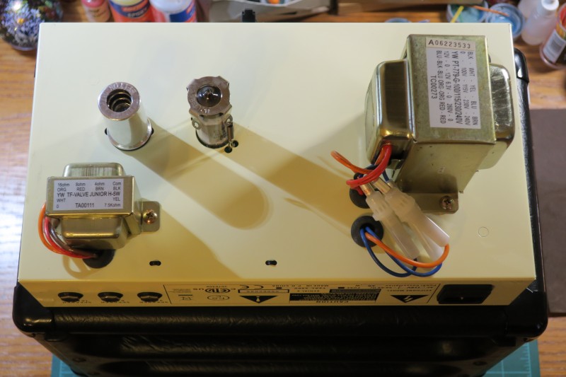
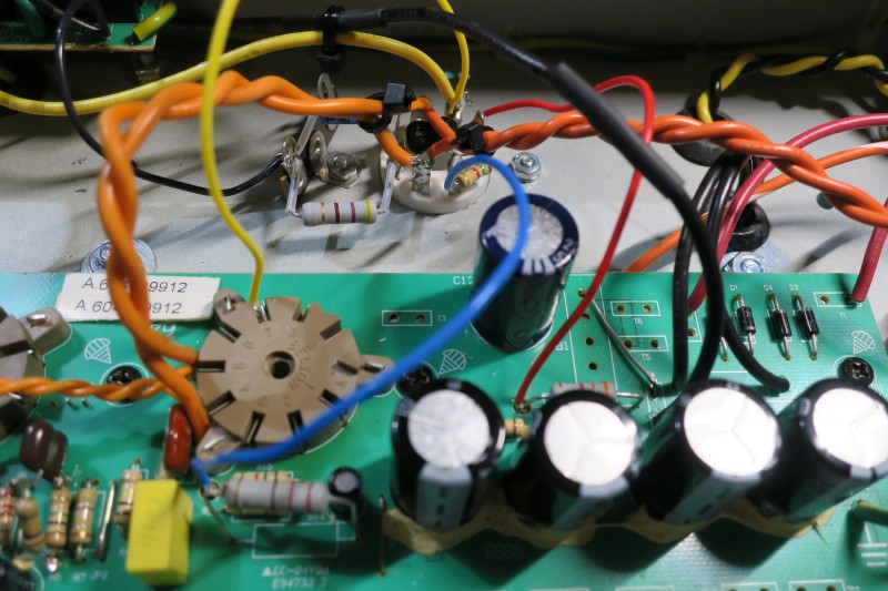
On the upper left are leads from the output transformer. Four of the leads from the secondary (ground, 4, 8, and 16 ohm) are connected to the speaker jacks. The black and yellow primaries are connected to the choke output and the power tube output. More on these later.
 |
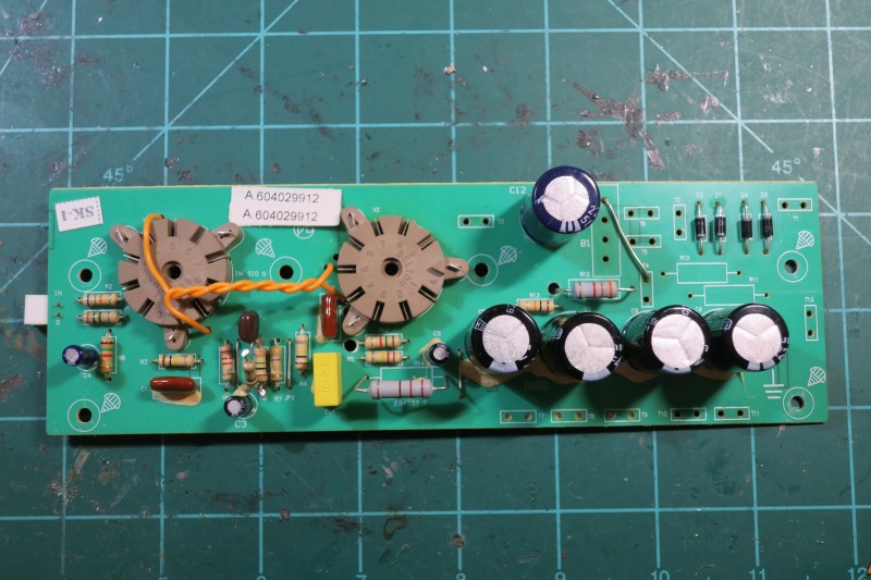
The red wires "B+" wires of the secondary come in through the case near the lower right and attach to the circuit board near the diodes at the top right. The wires are called "B+" because in the old days, they came from the positive lead of a battery. The name stuck. The B+ leads connect to those 4 diodes on the upper right of circuit board. The diodes make a diamond-shaped diode bridge which rectifies AC into a DC voltage for the B+ DC power supply.
The four big black capacitors in the center of the board help smooth out the DC voltage. These caps can withstand the high voltage (450V) of the B+ supply. They are also called "death caps" because they can kill you or give you a nasty electrical burn, so you must always discharge them before working on a tube amp.
You can also see the connection of the yellow and black wires for the primary inputs of the output transformer.
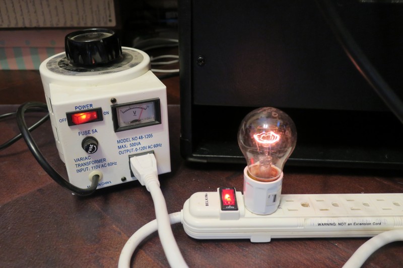 |
Shown in the photo is my guitar boot up safety equipment. The unit on the left is a variable AC transformer or variac. It can vary the wall power supply from 0 to 120 volts as controlled by the big dial on top and shown in the meter.
The unit on the left is my home-brew current indicator and limiter. It is a light bulb wired in series with one of the AC power leads. If the amp has a short circuit, the current through the bulb will light brightly, telling you to shut down the voltage. The light bulb filament is also a high power resistor, which limits current to the amp, at about the power rating of the bulb. Thus a 40 watt bulb will limit the power to the amp and protect it from frying. As shown in the photo, some steady state glow is normal.
At this point the amp did not fry, but it also did not produce any sounds. I debugged and found I swapped the yellow and black wires of the output transformer primary with the yellow and black wires of the secondary. Why they made these wires the same color is confusing to me. Once the wires were fixed, the new transformers and the components were sounding great. Joy!
 |
With the basic mods and the EL84 tube working, the next phase is to wire in the new 6V6 tube. The nice thing about this kit is that you can run with just one of the EL84 or 6V6, or both together. We will compare the different tube sounds later.
This photo shows an overview of the second tube hookup. Again, you can see the twisted orange heater wires bouncing from socket to socket. You can see the yellow output transformer primary is provided to both the EL84 and 6V6 plates. The black output primary wire is connected to the choke to provide power for the output.
Second you can see a resistor and capacitor connecting the cathode to a small standoff which is then connected to a ground on the output circuit board. The cathode (excited by the heaters) and the plate provide the river of power for the output.
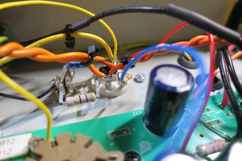 |
The red wire goes to the screens of the EL84 and 6V6. The screen is between the gate and the plate and controls the backsplash of electrons from the plate. This makes the tubes more efficient.
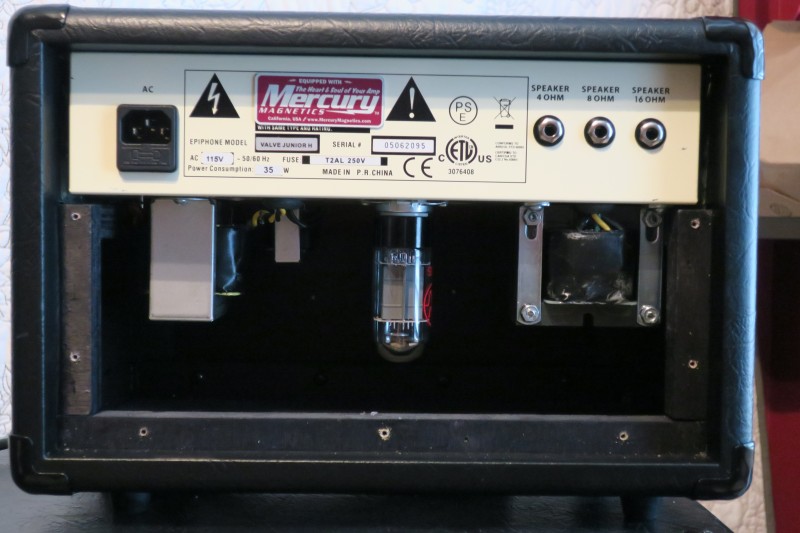 |
Also notice the red Mercury Magnetics badge announcing the glorious upgrades within.
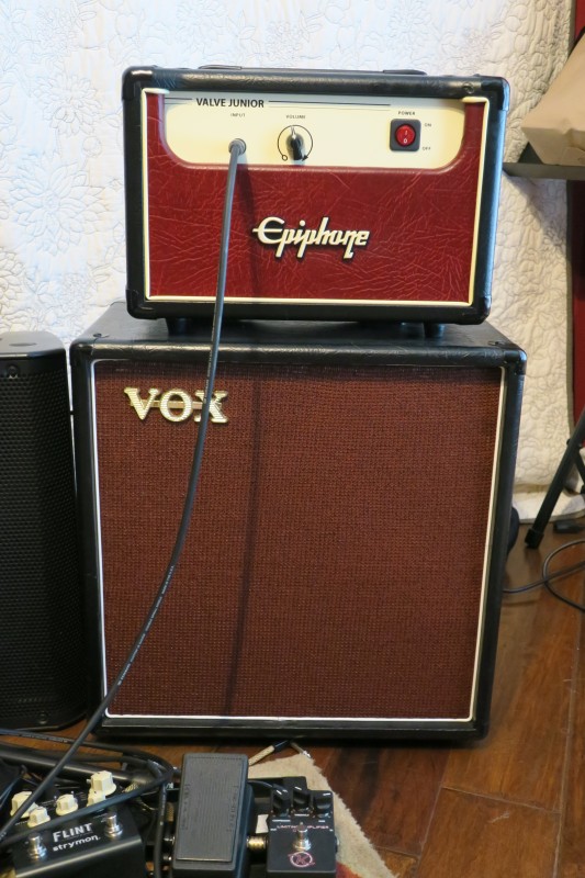 |
The cabinet below is an Epiphone Junior speaker cabinet, but it too has been modified. Similar to the amp head, the speaker cabinet is way overbuilt with thick birch plywood and metal corner guards. However, I enlarge the baffle to 15" and loaded the cabinet with a high wattage, 15" Celestion creamback. Then I added Vox colored grill cloth and a Vox logo. Why? Because that's how I roll.
Time to listed to some tones.
The recordings are done through different takes. Some of the versions are better or worse, but I hope it gives an idea of the final sound. Sorry, I am not a guitar master.
Thanks for visiting the site and reading the article. I hope you enjoyed the detailed photos and comments and had fun listening to the sound clips. More articles are found at the parent Guitars and Music page.