
This article shows how to use a USB cable connection to power a MIDI device. Why would you want to do this? These days USB sockets are a very common source of DC power. Many devices come with AC to DC converter transformers, and now hotel rooms, wall outlets, and automobiles are providing USB sockets as a source of DC power.
MIDI devices, mostly used for making music, often require a dedicated
wall transformer to give power.
Some of the newer MIDI devices can use a USB cable to provide power.
Some other MIDI devices can use the five pin MIDI DIN connector to provide
power.
Depending on your MIDI device, you might have 3 or more wires to the device.
This article shows how you can splice a cheap USB cable to a cheap MIDI cable
to provide power to your MIDI device.
Hopefully this saves you a cable or two and makes your music set up simpler.
|
|
For my application, I am trying to power a MIDI Solutions Quadra Merge box that allows multiple MIDI streams to merge into one MIDI input. I want a MIDI keyboard controller (Axiom 25) and a MIDI foot pedal controller (McMillen 12 Step) to input into the one and only input of my MIDI synthesizer (Roland SD-50). Unfortunately the MIDI synthesizer has only one socket, and I want more. Also, neither MIDI controller could provide power to the MIDI Quadra Merge.
According to the MIDI Solutions FAQ:
"You can connect an external +5V DC power source to the MIDI input of the MIDI Solutions product as follows: Connect the ground of the power source to the center pin of the MIDI input jack (pin 2), and connect +5V of the power source to the two pins on either side of the center pin (pins 4 and 5). The outermost pins may be left disconnected."
The diagram shows the connections.
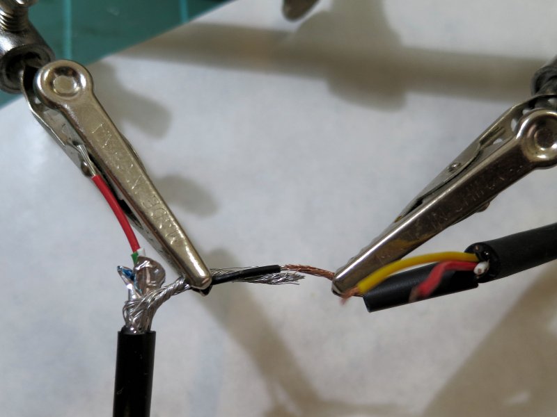
Connect USB ground (pin 4) to the MIDI shield (shield and pin 2).
If you are comfortable with schematics, splicing wires, and soldering,
that is all you have to know from this article.
If you would like more details and instruction read on.
|
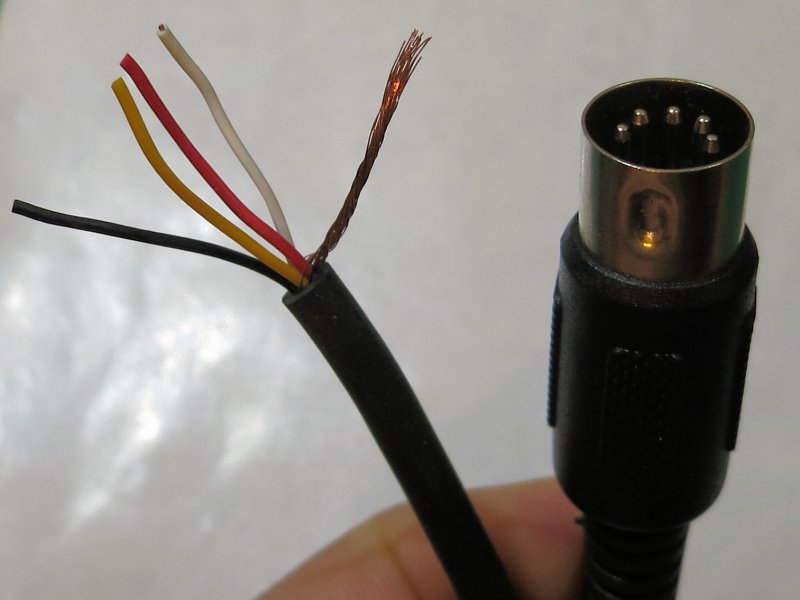
Using a multi-meter or a continuity light,
validate the copper braided sheath connects to DIN pin 2.
The black, white, red, and yellow wires connect to DIN pins 1, 3, 4, and 5.
Your wire colors may vary.
The conectivity is what is important.
|
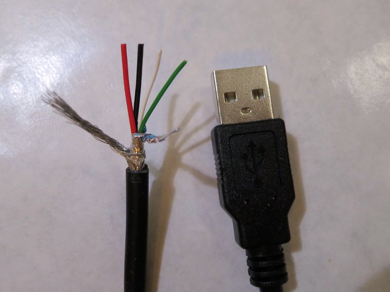
In a similar manner, cut a USB cable to length and identify
the wire connections to the connector.
With my USB cable, the sheath and the black wire are connected to USB pin 4.
The red, white, and yellow wires are connected to USB pin 1, 2, and 3.
|
|

|
Thanks for visiting the site and reading the article. I hope you enjoyed the detailed photos and comments and will have more fun as a result. More articles are found at the parent Guitars and Music page.