|
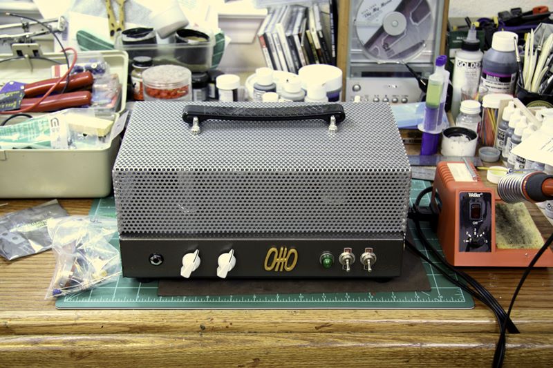
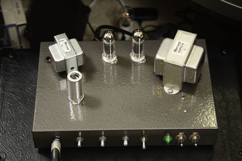
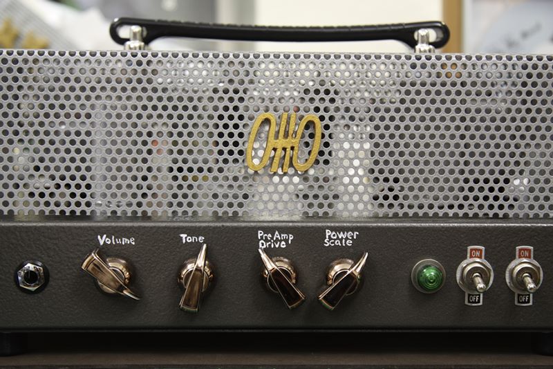
The basis of this power-scaled amp is a build-it-yourself kit guitar ampdesigned by Gerhart Amplification and sold by Guytronix.This design is a 12AX7WA preamp tube driving two EL84 power tubes in a push-pull configuration.The makers call this design the Ardmore, but affectionately I call my instance the Otto,and I have a detailed article of its building.The photo at right shows how I painted, enclosed, and gave a mock badge to the basic kit .
My messy hobby desk is about as clean as it's going to get. The London Power SB-84 Super Budget Power Scale kit is on the left.The trusty soldering iron on the right.Some music is on the playerLet's build this project!
 |
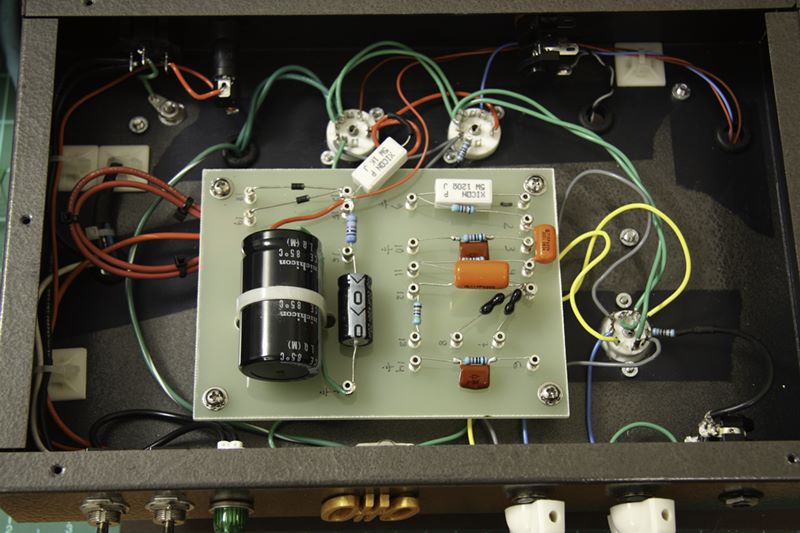 |
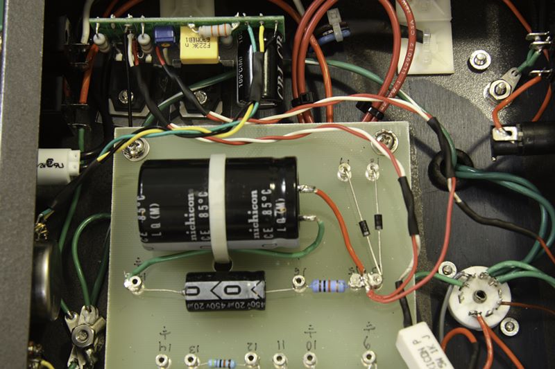
The large black cylinder is the "death capacitor" which isso named because it is huge and stores 400 V of energy ready tokill you if you touch it or other inappropriate, juiced parts of the circuit.The reason this cap is so large is that it has the task of smoothingout the AC voltage and helping to convert it to a nice level DC voltage.The red lead of the death cap leads to the DC supply posts.You can see about 5 different components connect to this spot in orderto get some power.
I've shorted out the death cap intentionally once, and the spark was strong enough to weld metal.If you work on tube amps, be sure you have a 5W 500 ohm resistor that you can useto drain the death cap and other parts of the circuit.
The other wires around the board are there to hook up the tube sockets, the supply transformers,and the front panel controls to the circuit.
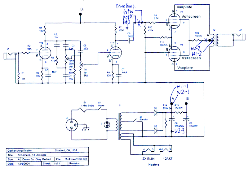 |
The top left of this diagram shows the preamplifier circuitry that is connected to the guitar jack at left.The top right of this diagram shows the power amplifier circuitry connecting to theoutput transformer and the speaker jack at right.The bottom of the diagram shows the power supply circuitry and howthe AC power from the wall socket goes through the power supply transformerand gets rectified by two diodes and the power smoothing capacitors.
At the top center is the attachment of the "Drive Compensation" potentiometer.This pot helps scale the preamp output to a lower level.In power-scaling, as the power supply level to the output tubes drops, sometimesthe preamp signal can get too large for the output tube gates.To control the amount of distortion in the output tubes this pot lets you leave the preamp signalat full blast (thus distorting the output tubes) or drop it proportionately.The drive compensation pot passively interrupts the preamp signal.The pot is independent from the rest of the power-scale circuit and couldbe added to any guitar amp project on its own.
The rest of the power-scale circuit attaches between the output tubes andthe output transformer.As I've mentioned, the power-scale circuit works by lowering the screen voltage to the output tubes.Thus, the input signal at the tube gate gets overdrives the screen voltage and goesinto the distortion zone.One loose end, the chunky 5 watt ceramic resistor R12,goes into the W2-2 pad of the power-scale circuit and then the W2-1 padattaches to the main DC supply rail.Then, W1-1 returns from the DC supply rail and attaches through W1-2 of the center tapof the output rail.Inserting the power-scaling circuitry here allows it to control the output tube screens and platevoltages, starving it off, and putting it into the overloaded distortion zone.
Another beefy potentiometer controls the amount of power scaling.I won't get into how the power-scale circuit does this, but suffice to say, the pot controls two large powerful JFET transistorsto control the power level.
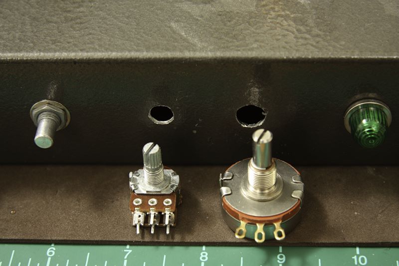 |
I paid close attention to removing metal filings from the drillinginto the amplifier case.Metal filings are the killers of guitar amplifiers.One filing can easily short out a 400 volt signal.I went through close to an entire can if aerosol dusting spraytrying to get every filing out of the project box.
 |
I don't know why my solder joints look so sucky these days.Ideally, solder joints should be shiny and flowing over wiresand pads, forming nice pools of solid connection withoutburning the components or the circuit boards.Perhaps because modern solder wires no longer have lead, they areless shiny than I am accustomed to.Perhaps my soldering iron is not hot enough.Yeech. I try my best, but many joints in this article look terrible.
 |
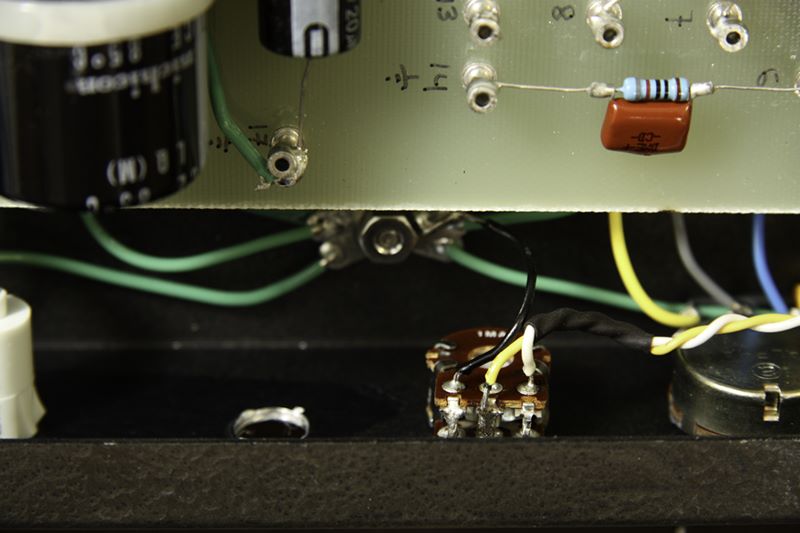
This connection proved to be my one mistake in the circuit hook-up.By hooking up the pot this way, the full preamp signal is sent when the pot is turned hard left.The diminished signal is sent when the pot is turned hard right.I prefer the opposite convention, so later on I reversed the yellowand white leads shown here - an easy 5 minute fix.
The wire color choices are arbitrary.I tended to use green or black for grounds, red for hot DC signals,and yellow or white for signals.I ran out of colors so this formula is not strictly followed.
Heat shrink tubing is used over splices to prevent short circuitswith other metal objects.The heat shrink tubing is also useful to group and hold wires together,for instance where you want a twisted pair to stay put.
 |
The remaining open connections are attach points for wiring in this circuit to your amplifier.W3 at the upper right attaches to the power-scale pot in the front control panel.W2 at the left attaches to the power tube outputs.W2 under the blue trim put attaches to the power transformer inputs.More wires will drop in here later in the article.
You might notice the straight wire connection to the upper left, replacing resistor R7.When Kevin O'Connor of London Power reviewed my designon the Power Scaling forums, he graciously checked for errors and told me that since my amp has an output resistor, I can omit this resistor.It's nice to have experts review your work.
Once again, sorry for the lame solder joints.It's a skill that I need to improve.
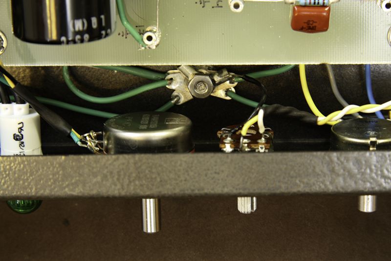 |
In the background you can see the star ground of the circuit getting mighty crowded.The star ground is the single attachment point to which all ground points are attached.If the entire circuit is grounded at one place, there is no chance forvoltage differences to introduce noise to the circuit.
 |
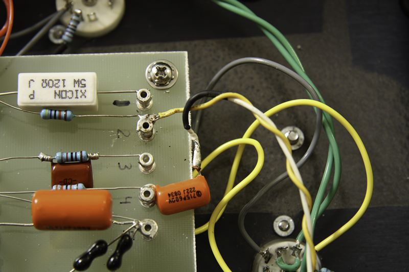
A twisted red and white pair of wires emerges from the W2 pad of the power scale circuit board.The white wire goes to the chunky 5 watt ceramic resistor R12 at the bottom right of the photo.The red wire attaches to the DC supply rail which is the double post slightly right of center.This connection interrupts the output power tube screens.
Another twisted read and white pair of wires emerges from the W1 pad of the power scale circuit board.The red wire also attaches to the DC supply rail.The white wire connects to the center tap of the output transformer which is the wireleading off the far right of the board.
 |
As if by magic, the amplifier started just perfectly.No sparks, no smoke, no short circuits.There also was no loud hum, no clickety clack-noise, just pure silence.I hooked up the guitar, brought up the volume and started playing with no problems.
Notice the light bulb glowing in the cluttered background at the top center of the picture.This is the current limitercircuit that I built inexpensively and describe in another article.Basically, this doo-dad puts a light bulb in series with the power supply to the amplifier.The light bulb acts as a resistor which will glow brightly if your amplifier is completely shorted out.
It saves you fuses and trips to the circuit breakers, but it also gives youa glimpse at the power consumption of your guitar amplifier.For instance, when you first switch on the power supply, the bulb goes verybright, and then dies off to a dull glow as the capacitors charge up.Then, when you switch on the output transformers, the bulb also goes verybright, and quiesces to the running current of your idle amplifier.Finally, the brightness of the bulb tracks the volume of your guitar playing.A very small volume has little light. Loud playing lights the bulb brightly.I'm surprised more consumer electronics don't have some sort of power consumption indicator.
 |
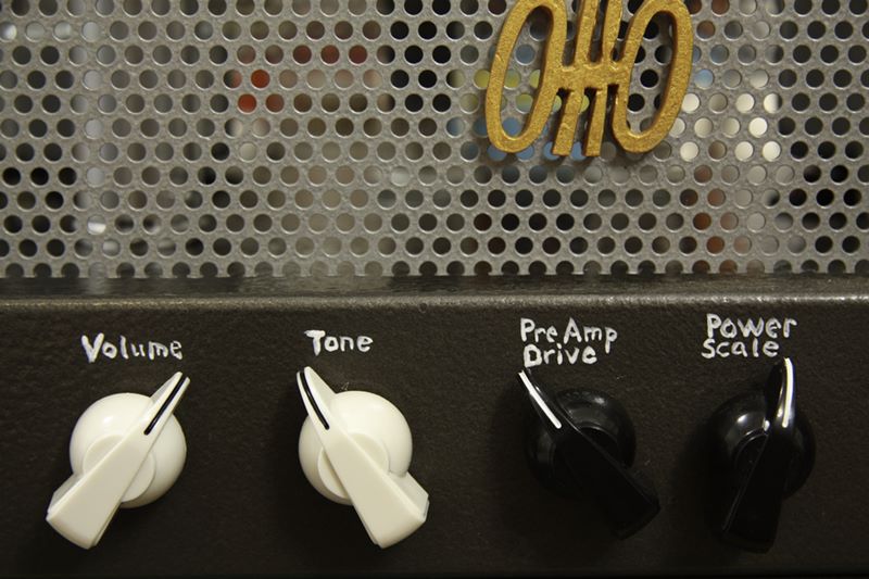
Eagle-eyed readers might notice the spacing of the rightmost black knobis slightly different.The other knobs are spaced 1.5 inches apart.If I had placed the rightmost knob also 1.5 inches apart, it would havebeen closer to the on/off light than the other knobs.So I cut down the spacing to try to group it closer with the other knobs.Unfortunately I might have mis-measured because now it lookstoo close to the other knobs, too far from the light.
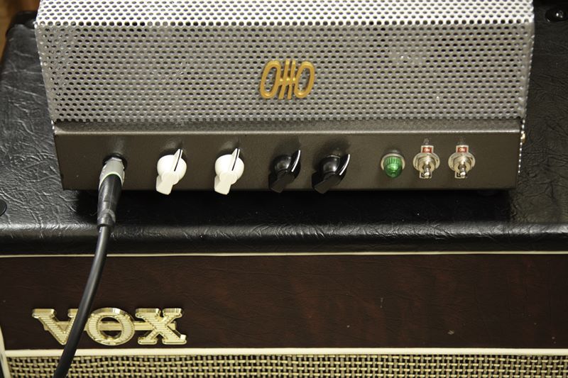
Vox aficionados might wonder what kind of speaker cabinet is shown.Well, it's not a Vox. It's an Epiphone cabinetwith new vinyl and a scavenged logo.The speaker in the cabinet is a 12 inch Eminence Red Coat Governor.
 |
 |
That concludes the construction portion of this article.Of course the main measure of any modification is the type and the qualityof the sound it produces.I can say that the amplifier performs perfectly.The unadulterated amplifier always had a very quiet noisefloor, most likely due to the quality components included in the kit.It also has very nice clean tones and is surprisingly loud for just 8 watts.The highs are very "chimey", very Voxy likely due to the similarityof this design to Vox guitar amplifier designs.These bright clean tones remain when you dial out the power-scale circuit.
The new modifications bring a whole range of sounds to the amplifier.It is very easy to get overdriven sounds and some dark heavy metal type crunch.The power-scale control allows you to determine how this overdrive is going to happen,whether it goes overdriven continually with every note, or whether you fall off some cleanpicking and light chords into the dark heavy distorted abyss when you vary your attack.
I hope to demonstrate the sound range in the next section.At this point I can say I am very happy with the London Power SB-84 Power-Scale kitmodification.
Thanks for visiting the site and reading the article.I hope you enjoyed the detailed photos and commentsand had fun listening to the sound clips.More articles are found at the parentGuitars and Music page.