Dan Becker's Power-Scaled Vox AC4 Amplifier Build
 |
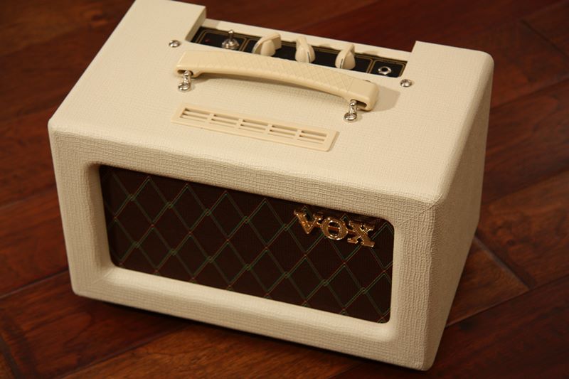
| The Vox AC4 TVH Guitar Amplifier |
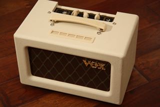
This article shows how I built a power-scaled tube guitar amplifier by making radical changes to a Vox AC4 TVH amplifier head.If you want to skip the build description and just hear the amplifier,just skip the article and jump to the sound clips.A Vox AC4 TVH is a small tube-driven practice amplifier release byVox in 2008.It is available as a head (shown here), an 8" combo, and a 10" combo.The circuitry is based on the AC4 amplifier that Vox released in 1961.Basically it is a single preamp tube (12AX7) driving a single power outputtube (EL-84) in Class A single ended fashion, for a whopping total of 4 watts out.In order to get the overdrive tone at lower volumes, Vox has includeda passive attenuator circuit that allows you to play at 4, 1, and 1/4 watts out.Unfortunately the resistive circuit keeps the tube running at max power,while coloring the sound and throwing off lots of heat.
Power-scaling is a technique for getting the overdrive sound of a tube-drivenamplifier at lower volume levels.London Power sells an SB-84 circuit kit, for use with EL-84 powered amplifiers,that bring down the supply voltages of the output tubes, while maintaining proper screen voltages.The preamp signal and supply levels and the rest of the amp circuitry are not affected.This results in a sound closer to the original cranked sound of the amplifier,although at a much lower loudness.This article shows how I gutted my Vox AC4 amplifier and added a power-scaling circuit.
 |
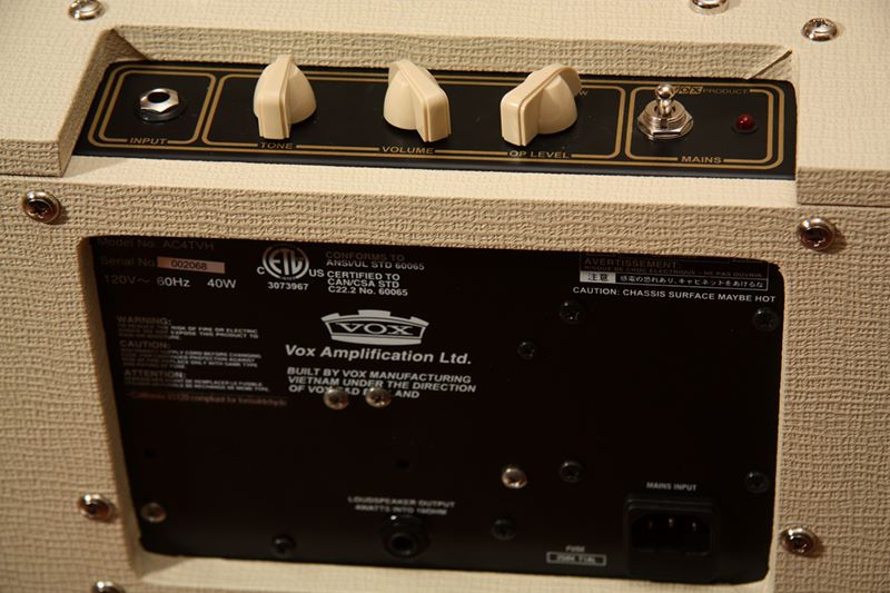
| Vox AC4 amp rear panel |
The Vox AC4 has a very nice build quality, great retro sounds and looks.As you see in the photo, the amplifier is built on a single "L panel" screwed to the cream colored Tolex cabinet.In order to save on parts and transformer costs, the amplifier hasa single 16 ohm speaker output, likely to try to steer you to thematching Vox 112 TV cabinet.Too bad both my home guitar cabinets are 8 ohm speakers.
 |
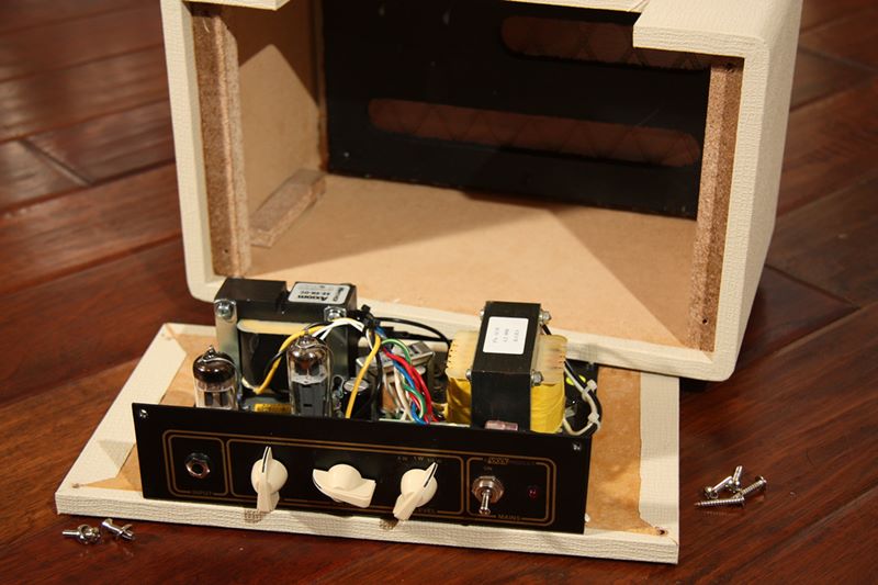
| Vox AC4 amp opened up |
Undo four wood screws and the back plate of the cabinet opens up.Undo four more screws and the L panel comes off of the cabinet back.As you see, this cabinet is made from particle board,inexpensive, but at least it is nicely made.I intend to put the amplifier guts in a new amplifier cabinetand sell off the Vox head cabinet. More on this later.
 |
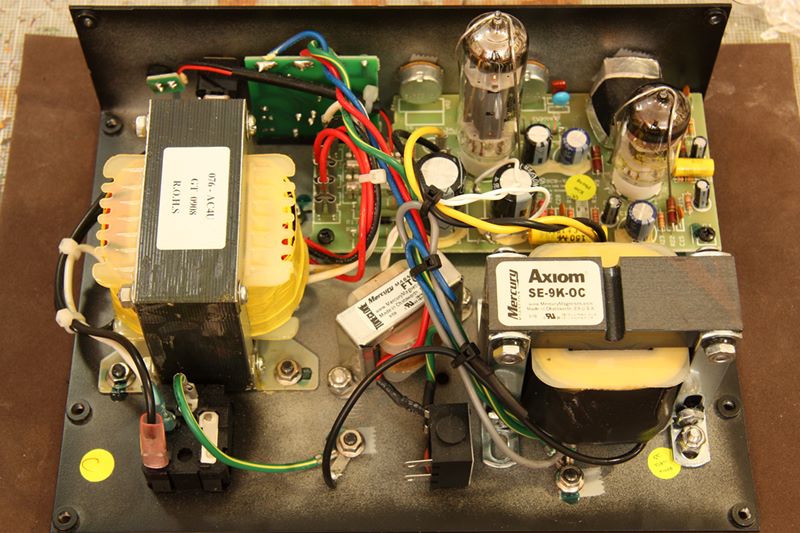
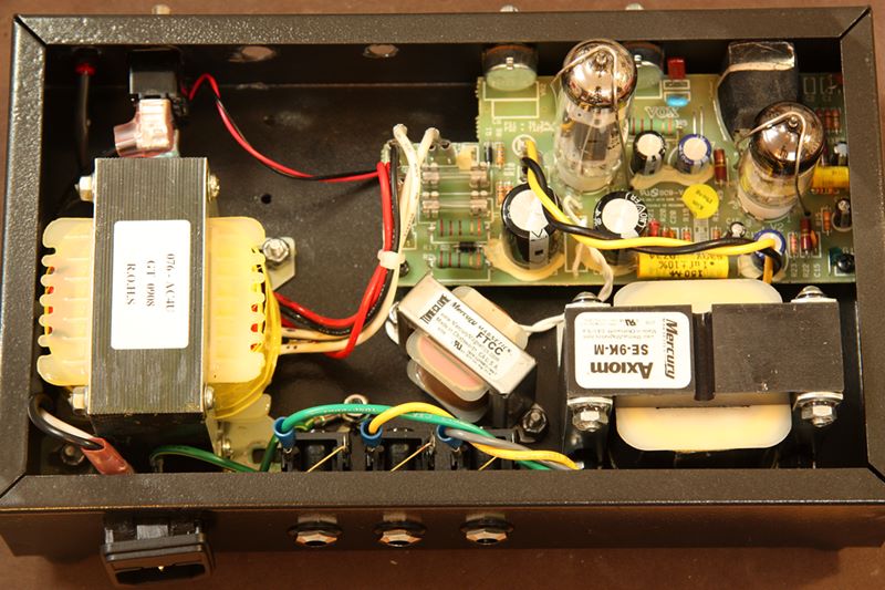
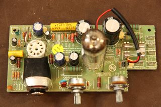
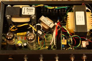
| Vox AC4 amp circuit panel |
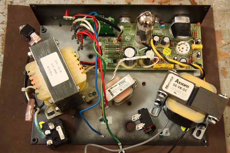
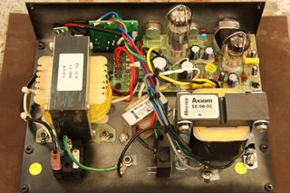
Here is a close up of the circuit panel.If this does not look like a standard Vox AC4, that isbecause it isn't!This version of the Vox is a Fargen modified amplifier.The Fargen mods include the new Mercury Magnetics output powertransformer (shown on the lower right), the Mercury Magnetics choke(the small transformer in the center), and a number ofother circuit mods such as the yellow capacitors in the signal path.The amp sounded good with these mods, but as a continual tinkerer, Iwanted to try for something else with the sound.Other major parts in this photo include the original power transformerat the left,the amplifier circuit board at the top right (with the tall EL-84 powertube and the shorter 12AX7 near the input jack),and the power attenuator board at the top left.
 |
| Vox AC4 amp disconnected parts |
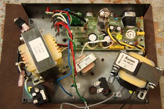
Here I have disconnected many of the pieces in order to get readyfor the amplifier relocation.Luckily, Vox used spade connectors for the transformers, andthis helped with the rapid connect and disconnect of these pieces.Notice how the choke transformer replaces R16 byfollowing the white wires from the choke to the circuit board.Chokes do a wonderful job of lowering AC hum noise, buta $27 choke is much more than a $0.10 resistor, andtherefore not an expense that most manufacturers are willing to bear.
 |
| Vox AC4 amp bare panel |
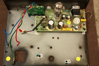
Most of the parts are cleared out.All that remains are the main circuit boardand the attenuator circuit board.Vox used a nice thick gauge piece of steel forthis panel.Too bad it is going away.
 |
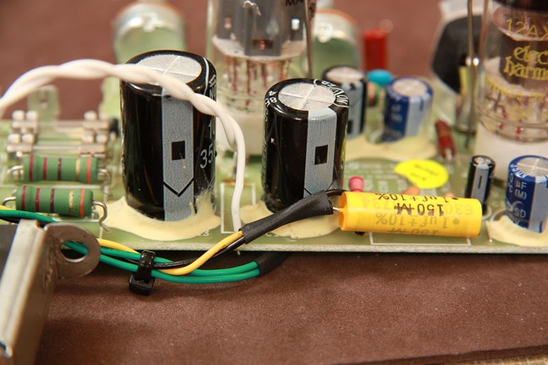
| Vox AC4 amp circuit board |
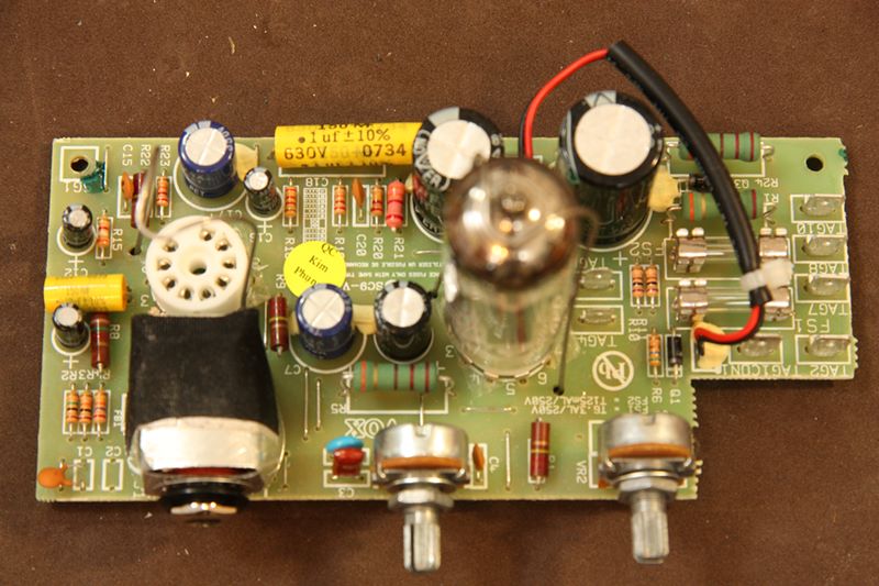
Here is a close up of the main circuit board.Notice the input jack and the volume and tone potentiometersare mounted to the circuit board.This layout requirement will determine our front panel spacingwhen we relocate to the new project box.The two "death capacitors" are the large caps at the topof the board.These caps maintain 400 volts even after the power isdisconnected.Ensure that if you work on guitar amplifiers that youalways drain these large power caps.A piece of wire will discharge them quickly with a large spark.A 5W 1k ohm resistor will discharge them in a second or twowith almost no spark.
I got a chuckle over the quality control inspector sticker"Kim Phung". That's the name of a popular Vietnamese restaurant here in Austin, Texas.
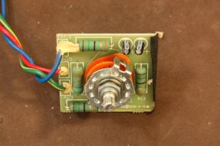 |
| Vox AC4 amp passive attenuator |
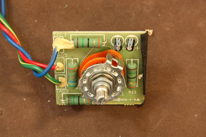
This is the power attenuator circuit board from the front.The pot has 3 detents to select one of the 3 resistorsto reduce the sound from 4 to 1 to 1/4 watts.This is not a preferred method of reducing output levelsas the resistors get very hot and the output power tubestill operates in full burn mode. Others think the sound is colored by puttingresistors in the circuit with the output signal -resistors are passive circuits, but speakers arevery complex impedances dependent on frequency.In any case, I am going to give it a try to replace thissimple board with a London Power SB-84 power-scaling circuit kit.
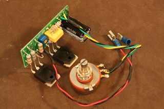 |
| London Power's SB-84 active power-scaling |
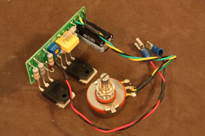
This photo shows the London Power SB-84 power-scaling circuit.The two large JFET transistors control the power supply voltageto the guitar amplifier output tubes.They are not in the signal path, but they do squash the power railsin which the power tube operates.The transistors get quite hot and have a metal back heat sinkand are screwed to the metal cabinet to dissipate heat.The large potentiometer controls the power scaling. Fully clockwisemeans full power to the power tube.Turning counter-clockwise lowers the power to the power tub.There is also a small blue trimpot on the circuit board which controlsthe screen plate voltage ratios.This is trimmed to keep the voltages at the original design level.The other connection are discussed next.
Update 2011-04-25: As mentioned below in the summary, I had trouble withthe amplifier causing some intermittent static crackling.While putting together my second power scaling kit for the Otto Amp,I noticed I put a diode in backwards on this Vox SB-84 board! This photo has the incorrect diode placement.Check out thereversed diodeof the Vox (note the black band on the glossy red diode, standing on end, about 20% in from the left edge of the board)versus the correct diodeof the Otto.I have corrected the diode, and now played the Vox for hours, and have not heard any static crackling.So be sure to double check you work.
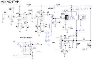 |
| Power-scaled Vox AC4TVH schematic |
Based on the instructions given in the SB-84 kit, this is the circuit schematicI developed for my Vox AC4.My changes are in blue, the orignal Vox AC4 circuit is in black (andwas developed by a number of us guitar amp enthusiasts with camerasand circuit probes at the Vintage Amps forums).Each amplifier has a different schematic, so it is up to the userto adapt the power-scaling kit to their individual amplifier.Luckily there is a Power Scaling forum to discuss amplifiers and power-scaling.Kevin O'Connor, the owner of London Power and writer of many excellentguitar amplifier design books,graciously participates in the forums.He checked and corrected a few mistakes I had in my original design,and thanks to his collaboration, I was able to come up with the schematicyou see here.I posted my work back to the forum, and several others have contacted me and asked questions.Apparently there are some other power-scaling fans out there.Here are a few points about the circuit.1) The kit provides a second smaller potentiometer, marked Pot X/W/O in the diagram, tocontrol "drive compensation". This controls the gate signal into the power tubeand can attenuate the guitar signal to power tube. Basically, if you turn the powerway down, the guitar signal can clip, so this pot helps control that.2) The voltage to the output transformer, marked W1-1 and W1-2 in the diagram, isinterrupted and controlled by the SB-84 kit. Indirectly, this affects the swing of the power output plate voltage Va.3) The screen voltage Vs, marked W2-1 and W2-2 in the diagram, is interrupted and controlledby the SB-84 kit.Vs and Va are kept in sync by the SB-84 kit to control the output voltage.
 |
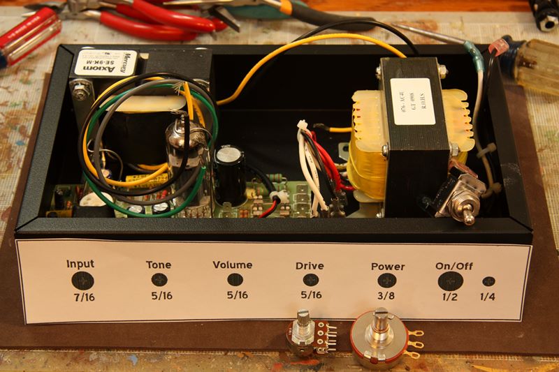
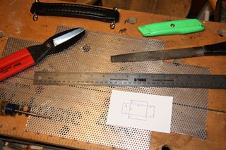
| Front panel template |
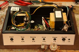
This photo shows the 10" by 6" by 2" (25cm x 15cm X 5cm) steel project boxin which I am stuffing my Vox AC4.The components are loosely placed in the project box to see if they fit.As you can see, it is a very compact arrangement.Additionally, I have to match the guitar circuit boardjack, tone, and volume spacing to the front of the box.Given this spacing, I lay out the SB-84 drive and power pots,and the on/off toggle and LED hole ina somewhat even spacing.I make a paper template of it all to help with the drilling andthe punching of the holes.
 |
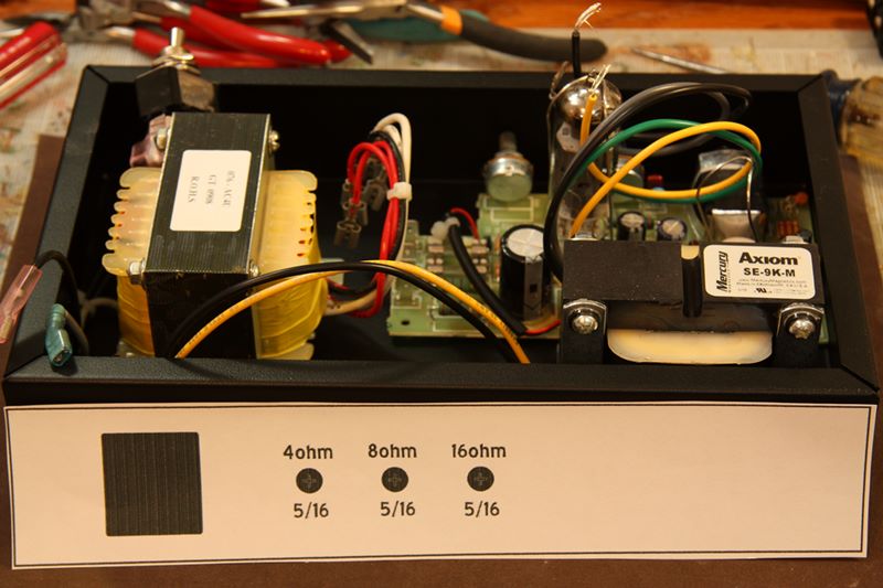
| Rear panel template |
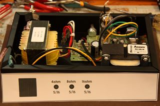
Similarly, I make a paper template for the rear panel.The power cord input socket is to the extreme left.Another upgrade I am adding is a three tap output transformerto allow connection of 4, 8, and 16 ohm speaker cabinets.Now you see another method to my madness!The original Vox AC4 has but one single 16 ohm output tap.That output tap feeds into the dedicated power attenuator board.No additional taps can be added, at least no taps with powerattenuation.Using the SB-84 power-scaling kit, I am able to move thepower attenuation from a spot after the power transformer toa spot before the power transformer.Now the SB-84 power-scaling kit controls the volume and powerto all three outputs!
 |
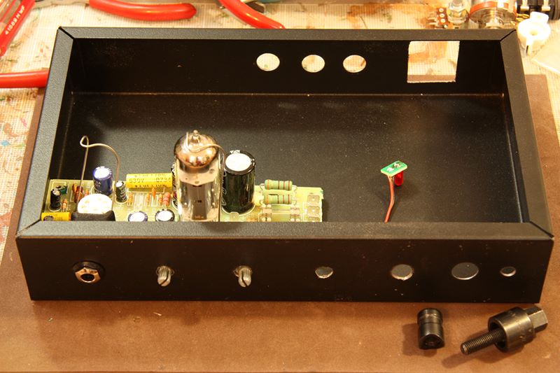
| Project box punching |
This photo shows all the front and rear panel holes.I have a single steel punch that makes a 5/16" hole,which is the size of most guitar input and speaker output jacks.The three piece punch is shown in front of the project box here.The punch makes a nice clean hole.The other size holes, for example the 1/4" hole for the LED lamp, I make with a drill press.The drilled holes are not quite so clean, and must be filedand deburred with a hand held grinding tool (e.g. a Dremel tool).This photo also shows the paint job I did on the project box.This is Krylon Hammered Black enamel spray paint.It has a nice semi-gloss sheen to it, with a smooth texture,kind of similar to office furniture or a file cabinet.
 |
| Roughing in components |
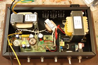
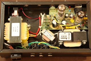
This photo shows all the parts layed out in the project box.All the pots and switches are fitted at the bottomof the photo.The three output jacks and the power supply socketare fitted at the top of the photoThe SB-84 power-scaling board is on its side rightof the main amplifier board.
 |
| Mains and output jacks |
Here is another view which I include to illustrate two mistakesand why taking photos of your projects can be helpful in post-analysis.Mistake number one: the power socket at the bottom right has no room to fit!I jam it in, but it bumps against my location for the power transformer.It stays in place by friction, but the tiny plastic latches of the socketcannot grab and lock onto the project box.I have to be careful when removing the power cord, that I don'tyank out the socket with the cord.
Mistake number 2: the output power jacks are wired to the outputtransformer (as seen by the green, yellow, and gray wires), but the tipconnector is opposite the wire has been wired to ground (as seen bythe diagonal brass wires).What was I thinking?I know on guitar input jacks you do this sort of wiring so thatwhen there is no guitar jack in the socket, the input socket isgrounded to reduce any sort of hum.However, on an output socket, having no jack in it will cause ashort of the tranny to ground.Luckily I caught this output-transformer-destroying mistake beforeI turned on the amplifier. You will see these wires are absent in subsequent photographs.That would have been a $100 mistake!
 |
| Drive attenuator |
This photo shows the drive compensation pot connection to the amplifier.The yellow cap is C18 on the circuit diagram.The guitar signal from C18 is controlled by the SB-84 drive compensation potand then sent back through R21 to the gate of the power tube.
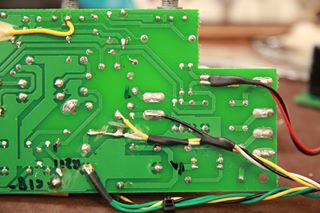 |
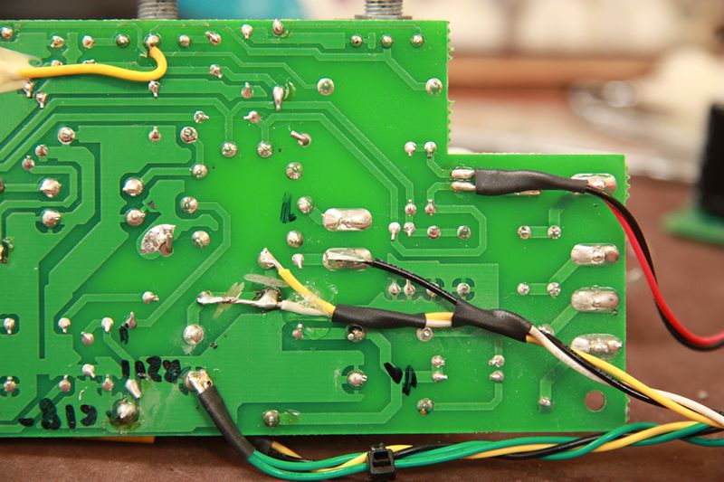
| Screen interrupt |
This photos shows more of the connections to the Vox AC4 amplifier circuit board.The green wires at the bottom are the return from the drive compensation pot.The black, white, and yellow wires are the W2-1, W2-2, and W2-3 screen connections to the power tube.Inadvertently, I cut the wrong land to the power tube,and I fixed the error by extending the white wire.The correct land to cut is shown between the white and yellow wiresolder joints.This is the only land you have to cut to add this power-scaling kit.The black wire simply connects to a convenient ground.The three wires are strain relieved by some heat shrink tubingand a bit of hot glue to keep it mechanically connected to the board.
 |
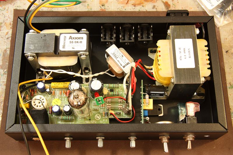
| Fully connected circuit |
Here is the amplifier circuit fully connected.Luckily it all fits.Some of the mod wires might seem a little loose or excessive.I try to keep the signal wires (like the black and yellow leadsto the output transformer) away from the power wires (likemost of the connections from the SB-84 kit to the amp board).Luckily, there is no hum or excessive noise in the finished project.
 |
| Amplifier bird cage cover |
With the amplifier nearly completed, I still have to work on the cosmeticsand packaging of the project.This photo shows the making of the aluminum "bird cage" hood for theproject box.It is a perforated aluminum sheet (0.063" thick with 0.125" holes and0.1875" stagger) purchased from Online Metals.The sheet is 12" by 24" (30cm by 60cm), but when you cutit down to the 5 sides of a rectangular box, it is about 10" by 18".The sheet cuts easily with tin snips and folds over the edge of a tableto make the hood.In yet another silly mistake, I originally miscut one of these sheetsand had to order a second one.The plan was sketched on an index card as shown in the photo.In my enthusiasm to make the cover, I added up the width dimensions 6 + 2 + 2 andcame up with 8 inches wide - wrong!Too narrow and ruining the sheet.Moral: calculate twice and cut once.
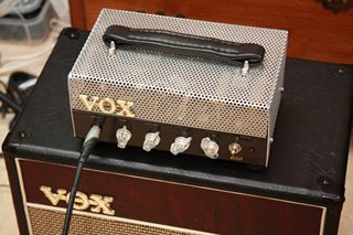 |
| Completed amp |
This photo shows the completed amp.Originally I was going to paint the perforated sheet cover, butmy wife said she like the raw brushed aluminum, so I left it bare.Many of the accessory parts are from Antique Electronic Supplies.The handle is real leather and connect to the cover viasimple machine screws and nuts.The clear plastic chicken head knobs look good against the black body.The Vox logo is plastic and is friction-fitted via twoplastic sprues into the aluminum sheet.
Like the faux Vox cabinet below it, this amplifier is nota Vox product.Perhaps I can fool some gearheads that it is the latest prototype.
 |
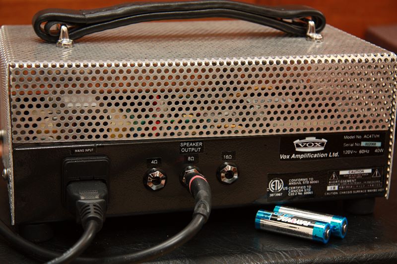
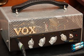
| Rear panel with AA batteries for size comparison |
This photo shows the rear of the guitar amp. As you can see from the comparative size of the AA batteries, itreally is a compact tiny guitar amplifier.No bigger than a box of shoes.The printing on the amp cabinet was done by the decal method.I bought white decal paper,and printed the logos and text white on black on the decal paper.Then I sprayed the paper with gloss enamel to make a wasteproof film over the decal.Then I cut the decal and dissolved the backing in waterand slid the decal onto the amp box.Aside from the text labels, I also scanned a few legalwarnings and logos to make the amplifier look official.
 |
| Front view with AA batteries for size comparison |
In summary, the most important consideration is how the amp sounds.Like any home project, being the creator, I take immense pride in my accomplishment,but I can also see the mistakes and problems in the finished product.First of all, when the amp is warm, it sounds excellent.Very chimey Vox highs and perfect control over the drive into distortion.The amp is also dead silent and nearly immune to room and guitar noise.However, at this moment the amp is plagued by some intermittent static.It only happens for 15 to 30 seconds and disappears, and it only shows uptwo or three times an hour.The static can disappear for weeks of playing, and then it will show upcontinually for a few nights.I'm sure this issue is the result of one of my cold solder joints somewhere,and I will someday fix it,but at the moment this is one of the bugs in the hardware.
Update 2011-04-25: After nearly a year and some discouragement, I finallyfigured out what was causing the static crackling. While putting together my second power scaling kit for the Otto Amp,I noticed I put a diode in backwards on this Vox amp! Check out thereversed diodeof the Vox (note the black band on the glossy red diode, standing on end, about 20% in from the left edge of the board)versus the correct diodeof the Otto.I have corrected the diode, and now played the Vox for hours, and have not heard any static crackling.So be sure to double check you work.
The power-scaling kit works like a dream.It enables the amp to get great overdrive at very low volume levels.The overdrive sounds good at full volume and reduced volumeI think I will eventually add this kit to the Otto Ampthat I built earlier this year.That amp is also SB-84 based, but it has two output tubes in a push pull arrangement.
Sound clips
Here are some clips I recorded on the power-scaled Vox AC4.Please be forgiving about the clips.I am a beginning guitarist, and I was in a bit of a rush to record these, butI hope they give you an idea of the flavor and the sounds thatare possible with the amp.All clips recorded via the AC4 amp, Epiphone Casino guitar, closed-back 12" Eminence Red Coat"The Governor" cabinet, Shure SM-58 beta mic, and Edirol UA-25EX DAC.No processing is applied to the recording except to normalize the volume level.
- E Minor clean neck - this is an E minorscale and chords played on the neck pickup, clean, with low drive and low volume.
- A Minor dirty bridge - this is an A minorscale and chords played on the bridge pickup, dirty, with higher drive and high volume.
- Smokey Robinson's My Girl - this is a few chordsfrom Smokey Robinson's "My Girl", played cleanly at lower volume levels.
- Tom Petty's Here Comes My Girl - this is a few chordsfrom Tom Petty's "Here Comes My Girl", played with a lot of drive, and the power scaling ofthe output tub turned down, so there is a bit of overdrive at lower volume levels.
- Paul Westerberg's Sadly Beautiful - this is a few chordsfrom Paul Westerberg's "Sadly Beautiful", played with a lot of reverb from a Tech 21 NYC reverb pedal.
Thanks for visiting the site and reading the article.I hope you enjoyed the detailed photos and commentsand had fun listening to the sound clips.More articles are found at the parentGuitars and Music page.